SFPTotal Wizard

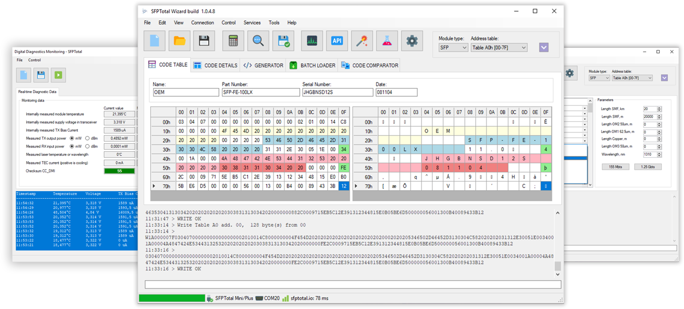
Official software

Download SFPTotal Wizard 1.0.5.3

SFPTotal devices are full-compatible with official software SFPTotal Wizard which provides a convenient interface that allows to read, decode, edit and write changes to the memory of optical transceivers GBIC, SFP, SFP+, SFP28, XFP, QSFP+, QSFP28 and QSFP-DD form factors.

The software is available for free download. SFPTotal Wizard can be used for editing code files without connecting to the original device.

Running in the MS Windows environment and uses Microsoft .NET Framework 4.5 or above.

Supported OS:

Full support:
Windows 11/10 Windows 8.1 Windows 7 SP3
With restrictions:
Windows XP up to build 1.0.3.5
In development:
Linux Mac OS


Drivers for devices


Software SFPTotal Wizard is used for operating with vendor code of transceivers different form-factors in accordance with generally accepted standards. SFPTotal Wizard works over SFPTotal protocol and is full compatible with original SFPTotal devices. The software supports next features and opportunities:

  • Read and coding vendor code
  • Automatic calc checksum
  • Import code from file and export to file
  • Support for the entire address space of transceivers
  • Decoding transceiver parameters in accorance to MSA
  • Setting parameters using config-bit
  • Coding transceivers with write-protection using a password
  • Coding transceivers using a script
  • Search password for write-protected transceivers
  • Reading Digital diagnostic monitoring registers
  • Batch coding optical transceivers
  • Checking a code compatibility options
  • and much more.

There is need a PC with USB 2.0 port to connect SFPTotal coding board. The coding board operates through a virtual serial port and could be run on any operating system, using specialized software to connect to the virtual serial port.

You can use the SFPTotal programming boards through a special software SFPTotal Wizard on Windows operating system.

To run application SFPTotal Wizard requires an operating system Windows 7 / 8.1 / 10 / 11 with pre-installed Microsoft .NET Framework of version 4.5 or above.

Download Microsoft .NET Framework directly from the official website: http://www.microsoft.com/ru-ru/download/details.aspx?id=17851


Installing driver for SFPTotal Mini / Plus
  1. Download the driver for coding boards SFPTotal Plus and SFPTotal Mini.
  2. Unzip archive with driver and certificate to new folder.
  3. Start cmd.exe under Administrator permissions.
  4. Go to new folder with unzip files using command:

    cd %PATH
  5. Execute following commands to add SFPTotal certificate in Trusted Publishers:

    .\cer\certmgr.exe -add .\cer\SFPTotalTeam.cer -s -r localMachine ROOT
    .\cer\certmgr.exe -add .\cer\SFPTotalTeam.cer -s -r localMachine TRUSTEDPUBLISHER
  6. Execute following command to import driver in the system:

    pnputil -i -a "SFPTotal Device.inf"


Installing driver for SFPTotal Whitle
  1. Download the driver for SFPTotal Whistle.
  2. Install downloaded packet.
  3. Connect SFPTotal Whistle to PC.

File controls

  • Reset file
  • Open code from file
  • Save code as ...
Service buttons

  • Calculate Checksums
  • Read code button
  • Write code button
  • DDM
  • API request button
Page select controls

Use these controls to select module type and page for read and write operations.

Code editor

CODE TABLE tab contains editor area of current code presented with two equivalent grids in HEX and ASCII formats.

Code details

CODE DETAILS tab contains table with decoded binary parameters for the Serial ID page code.


There no need any special settings for connection SFPTotal Plus and SFPTotal Mini.

Automatic mode

Leave Serial port number is empty and set flags Automatically search device for connection and Keep connection active in passive mode for auto connection to the board before execute the operations.

Manual mode

You should unset flag Automatically search device for connection and press Refresh to detect connected programming boards in manual connection mode. Set Serial port number in accordance to connected device and press Save to apply this settings.


SFPTotal Wizard provides interface to read all main address spaces of transceiver. It's recommended you familiarize yourself with transceivers memory mapping in the Transceiver memory map

  1. Connect a coding board to PC
  2. Run SFPTotal Wizard
  3. Plug-in a transceiver to the coding board port
  4. Select Module type
  5. Select Address table for reading
  6. Use menu Control - Read from transceiver or special button on general window.

If the data have been read without any error, the software show READ OK in the operation log area. Result of the reading will be shown on software's window. Read data will be presented in HEX and ASCII grids.


The software supports write operations to all available address spaces of transceivers.

There are have read-only and write-protected areas in transceivers memory. It's recommended you familiarize yourself with transceivers memory mapping in the Transceiver memory map

Follow next steps to do the write:

  1. Connect a coding board to PC
  2. Run SFPTotal Wizard
  3. Plug-in a transceiver to the coding board port
  4. Select Module type
  5. Select Address table for reading
  6. Use menu Control - Write to transceiver or special button on general window.

When the software send write command, the coding board execute write sequence, then read the same area after write done and return read data to the software.

The software compares written data and response after operation complete and shows the result.

If the data have been written without any error, the software show WRITE OK message in the operation log area. Result of the write will be shown on software's window.

WRITE FAIL

This response means that write process was unsuccessful. WRITE FAIL appears when you trying to write to write-protected transceiver or read-only area.


Serial ID page contains two checksums CC_BASE and CC_EXT which should be calculated after doing any changes in the code. These checksums are used to verify the integrity of the main transceiver code where declared configuration, vendor name, part number and serial number of transceiver.

Use menu Edit - Verify checksum to check values of CC_BASE and CC_EXT for the code. The fields in editor area will be green when checksums are correct and red when are not.

For default, the software automatically checks these values when you making changes in the code. You can disable this feature with flag in menu Edit - Autoset checksum.

Use Edit - Set checksums or special button on general window to recalculate and set correct checksums for the code.


Most 10G, 40G and 100G optical transceivers are write-protected and require password entry to unlock Serial ID page for changes.

The software supports write to write-protected transceivers using a password (MSA SFF-8472). You can use passwords length 4 bytes. Password entry doing in hexadecimal format using uppercase letters (A - F) and numeric (0 - 9).

For example:

00000000 00001011 AAABACAD FFFFFFFF

For default, the software doing the write without entry a password. To set up a password entry preferences you have to use menu Control - Set a password.


Set flag Entering the password before writing data and set password entry preferences to activate the function.

Standart preferences for coding SFP and SFP+ transceivers:

  • Table address: A2
  • Password address: 7B
Standart preferences for coding XFP and QSFP transceivers:
  • Table address: A0
  • Password address: 7B

Use SAVE button to apply the preferences or press Cancel.

After set password entry preferences, the software will do the write using a password when you press write button as it works for Write code

Note

If you used scripts before this, there is need to reset script preferences with menu Control - Write using a script - Reset script


Some transceivers don't support MSA standards to implement write-protection functions. Therefore, it is not possible to write to the module, even when the password is well known.

For example:

  • The software returns WRITE OK but the transceiver doesn't save changes after power cycle
  • Transceiver requires specific command after write to commit the changes
  • Transceiver use unspecified address to apply the code changes
  • Programmer returns QERR on write operations
  • Vendor algorithm require more than two operations

In that case you have to build a script file and provide correct sequence for success write into transceiver.

What is a script?

Scripts are a special mechanism that do the sequential transmission of instructions to programmer which execute commands for writing and reading code from the transceiver's memory. Scripts are used in the case when it is necessary to implement a specific transceiver programming mechanism, the writing algorithm in which differs from the standard and requires a number of special actions to successfully save the code changes in the transceiver's memory.

The script is a text file, in which each individual instruction begins on a new line. Instructions (commands) are implemented based on the SFPTotal command protocol in accordance with the device version.

Example:

w2A2007B0311223344
w2A000007F{00;7F}
w2A2007F0080
w2A200FF0001
PAUSE
R2A000007F

How to use a script?

Use menu Control - Write using a script - Select a script file to upload a script. The uploaded script will be used for doing write operation when you press write button.

Use menu Control - Write using a script - Reset script to reset a script.


The software provides DDM reading function for SFP transceivers.
Use menu Tools - Digital diagnostic monitoring


The software supports a function for search unknown password for write protected transceivers. The feature is helpful for quick check transceiver in short range of well-know passwords. There is available to use search in wide ranges or use brute attack using a dictionary of password.

How to use?
  1. Read a code from transceiver (or use random code template)
  2. Change at least one byte in the HEX grid. The code in software's window should be different than a code in transceiver's memory.
  3. Use menu Control - Search password
  4. Set parameters Table address (default: A2) and assword offset (default: 7B)
  5. Set additional options (if required)
  6. Set the range of password values or use dictionary of passwords
  7. Push Start button to run brute-force attack

Since version 1.0.4.6 the software supports automatic back up function for all available pages of transceiver before doing operations read or write.

Set flag in menu Control - Back up transceiver automatically to activate the feature.

The software will do the reading transceiver memory and save the dump of available pages to folder ./backup/ when you read or write anything. The dump file will be named using Vendor name, Part number, Serial number and SHA1 hash of Serial ID page the module.


Tools - General settings contains special parameters for working mode of programming board and the software.

Programming board
  • Speed rate - I2C data bus clocking frequency
  • Pause b/t operations (ms) - pause between blocks for write operations
  • Sequential write, bytes - size of block for write operations
Folders
  • Codes path for default - catalog for opening and saving codes
  • Scripts path for default - catalog for script files
  • API button URL - URL for API requests

here is a list of the most common error codes and their descriptions.

QERR:MTDOC

There were connected more than one transceiver to the coding board. Leave just one transceiver is connected to the board.

QERR:SCL / QERR:SDA

The I2C data bus line has been pulled to the ground by transceivers side. Data bus is blocked. Data transfer is impossible.

QERR:R20

The transceiver didn't response on address byte with read instruction. It keeps silence. This error appears when you read unavailable page or transceiver is not working.

If you got QERR:R20 on reading Table A2, it mean that module doesn't have Table A2 and doesn't support DDM which presented in this address space.

QERR:W20

Same as QERR:R20 for write operations.

QERR:W30

The transceiver responses on address byte with write instruction, but didn't response on data byte. It happens when transceiver didn't have a time to save previous data block and there was transfered new one block. In this case recommended to use General seetings to change a pause beetween transfer the blocks for write operations.

Also, this error could be returned when you try to write Table A0 for write-protected transceivers not using a password for unlock.

QERR:DEMO

The device is in demo mode. Write functions is limited.

Please, contact to Technical support to get an acvtivation key for your coding board.

QERR:x00

Unknown error on the databus.